



Why Parts That Fit in CAD Can Fail in Production
A tolerance stack-up is the combined dimensional variation across an assembly. Every individual part can pass inspection and still produce a button that will not click, a connector that misses its opening, or a gasket that does not seal.
That is because production parts are never exactly nominal. For an assembly to work, critical conditions such as clearance, compression, alignment, travel, and engagement must remain acceptable across the full range of variation.
Tolerance analysis should therefore happen before tooling, during key mechanical design stages. A small dimensional problem caught in CAD may take hours to correct. The same problem found after molds are cut can mean tool modifications, new samples, and weeks of delay.

Typical failure points include:
- Buttons with too much free travel or permanent pre-load.
- Gaskets with too little or too much compression.
- Displays with pressure marks or light leakage.
- USB-C and other connectors that do not align with enclosure openings.
How Tolerance Stack-Up Analysis Works
Start with one measurable functional requirement, such as button travel, gasket compression, connector alignment, or display clearance. Then trace every dimension and interface that affects it, including housing features, PCB thickness, adhesives, fasteners, and geometric tolerances.
Consider a simple handheld device with a button pressing a tactile switch on a PCB:
- Housing boss height: 8.00 mm, +0.00 / -0.10 mm.
- PCB thickness: 1.60 ±0.10 mm.
- Switch height: 0.60 ±0.05 mm.
- Button plunger: 5.70 ±0.10 mm.
The nominal gap is:
8.00 – 1.60 – 0.60 – 5.70 = 0.10 mm
Nominally, the design works. But at the worst dimensional combination:
7.90 – 1.70 – 0.65 – 5.80 = -0.25 mm
The negative gap means interference. Every part can still be within specification, yet the button may already be pressing the switch before the user touches it.
Engineers typically use three approaches to evaluate this risk:
| Method | How it works | Best use |
| Worst-case | Assumes every dimension reaches its limit at the same time. | Safety, sealing, low-volume builds, or conditions where failure is unacceptable. |
| RSS | Uses statistical variation from controlled manufacturing processes. | Higher-volume products with reliable process data. |
| Monte Carlo | Simulates many combinations using defined distributions. | Complex assemblies with several interacting variables. |
Worst-case analysis is conservative, while statistical methods can avoid unnecessarily tight and expensive tolerances. But statistical analysis is only useful when the underlying manufacturing data is reliable.
From CAD Tolerances to Production Validation
Tolerance analysis is not limited to plus/minus dimensions. Position, flatness, angular error, warpage, and datum selection can have an equal or greater effect on assembly fit. GD&T helps define these relationships based on how parts are actually located and assembled.
Manufacturing processes also change the picture. Injection-molded plastic can shrink or warp differently from a CNC or 3D-printed prototype. Temperature can shift dimensions when plastics, metals, and PCBs expand at different rates. A prototype that fits perfectly proves the nominal design, not the production process.
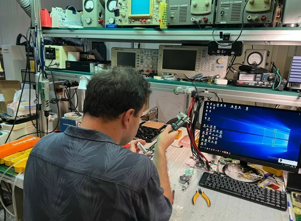
The goal is not to tighten every tolerance. Tight tolerances increase manufacturing and inspection costs. Engineers should identify the dimensions that actually control function and concentrate precision there.
Production then has to confirm that the assumptions were correct through:
- First-article measurements.
- Incoming inspection.
- Assembly measurements.
- Functional testing.
- Process capability data such as process capability index (Cpk) or process performance index (Ppk) where appropriate.
- Measurement of failed assemblies to identify shifted dimensions.
AJProTech reviews critical tolerance stacks before tooling, including buttons, seals, ports, displays, and enclosure interfaces. Finding these problems while the design is still in CAD is far cheaper than correcting them after production tooling has been released.
FAQ
How tight should tolerances be on molded plastic parts?
Tolerances should be driven by function. Locating bosses, sealing surfaces, and connector openings may require tighter control, while cosmetic or non-critical features usually do not. The achievable tolerance should also be confirmed with the manufacturer.
When should engineers rerun a tolerance stack-up analysis?
Rerun the analysis after changes to datums, materials, dimensions, suppliers, or manufacturing processes. It should also be revisited when first-article measurements differ from the assumptions used in the original analysis.
Is 1D tolerance analysis enough for an enclosure?
It works for simple gaps, heights, and compression paths. Use 2D or 3D analysis when position, angular error, warpage, pivots, or multiple datums affect the final fit.
Who owns the tolerance stack?
AJProTech, as the product team working on mechanical design, owns the functional requirement and stack logic. Suppliers contribute manufacturing capability, achievable tolerances, and inspection data. Both sides should review the critical stack before tooling is released.